Today we’ll be adding the electronics to your assembled robot chassis. In addition to the chassis, you need the following items from your kit:
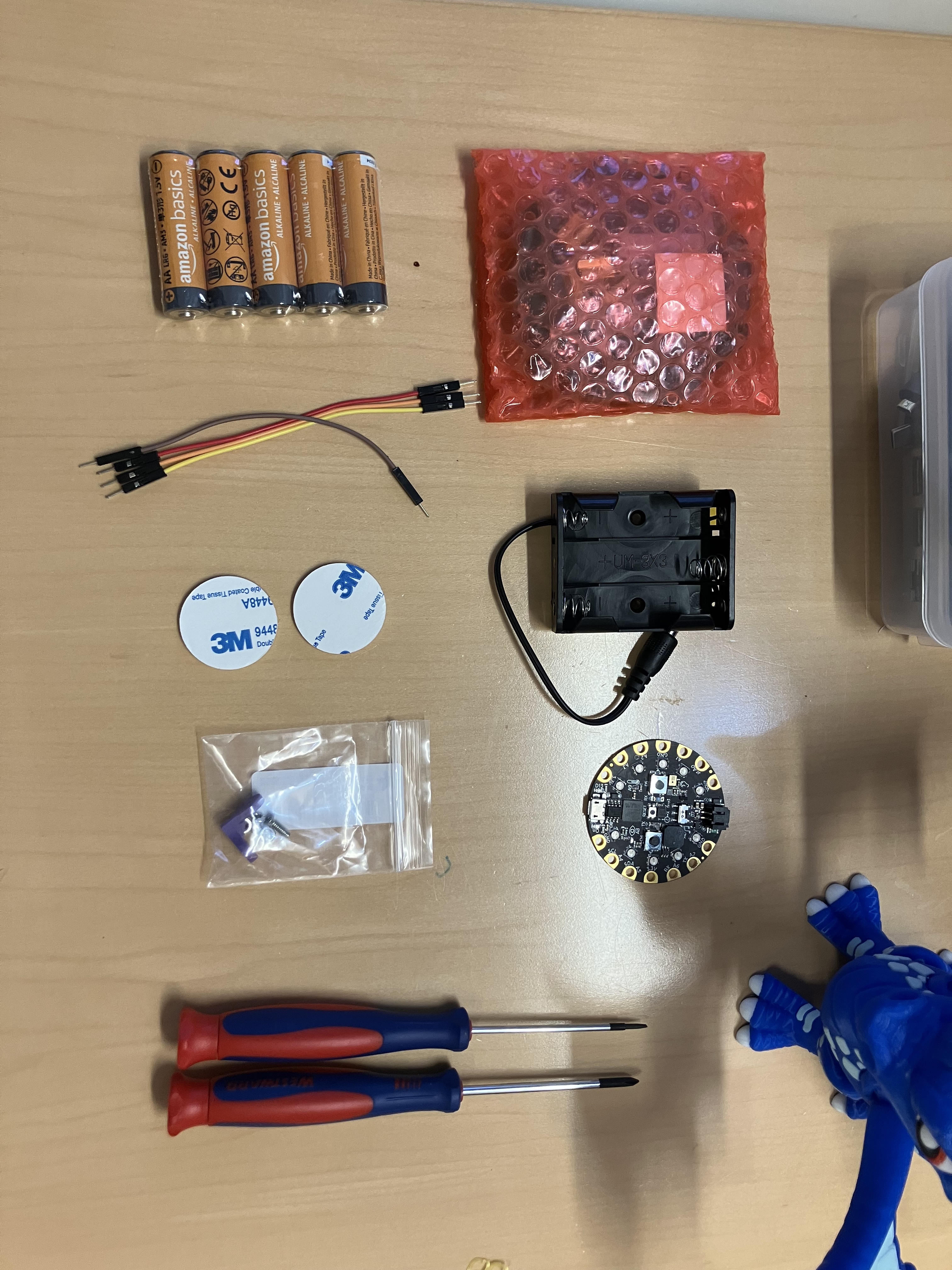
The CRICKIT board, which is wrapped in pink bubble wrap, your handy CPX, the AA battery holder and batteries, both small screwdrivers, four T-T jumper cables, two 3M stickers, and the little bag with the black plastic angle bracket and nuts and bolts in it (in the photo above and in the tutorial below, my angle bracket is light purple. Do not be alarmed.)
Hardware
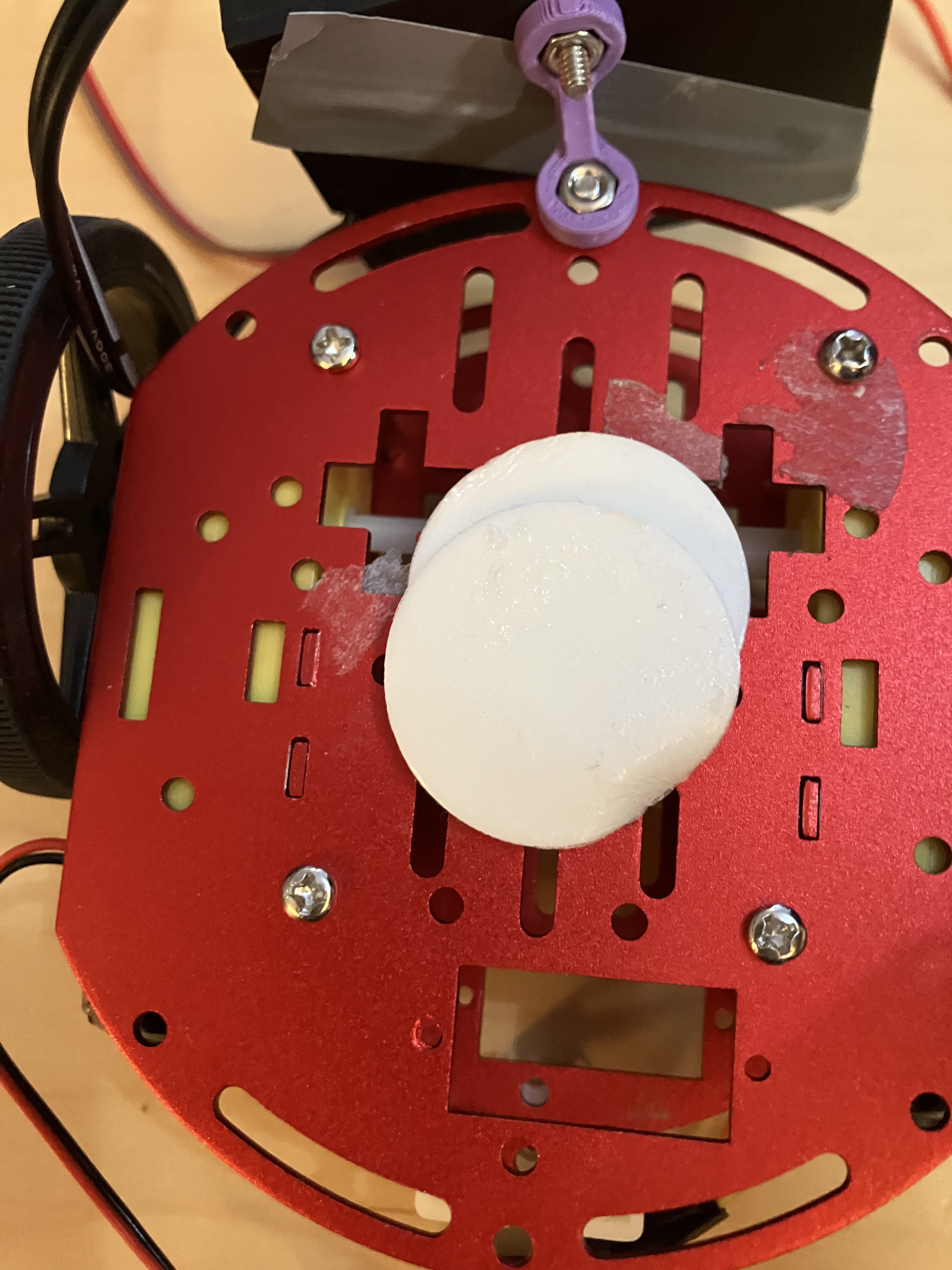
Start by verifying that the ball bearing wheel is connected properly- you want it centered at the front, like so:
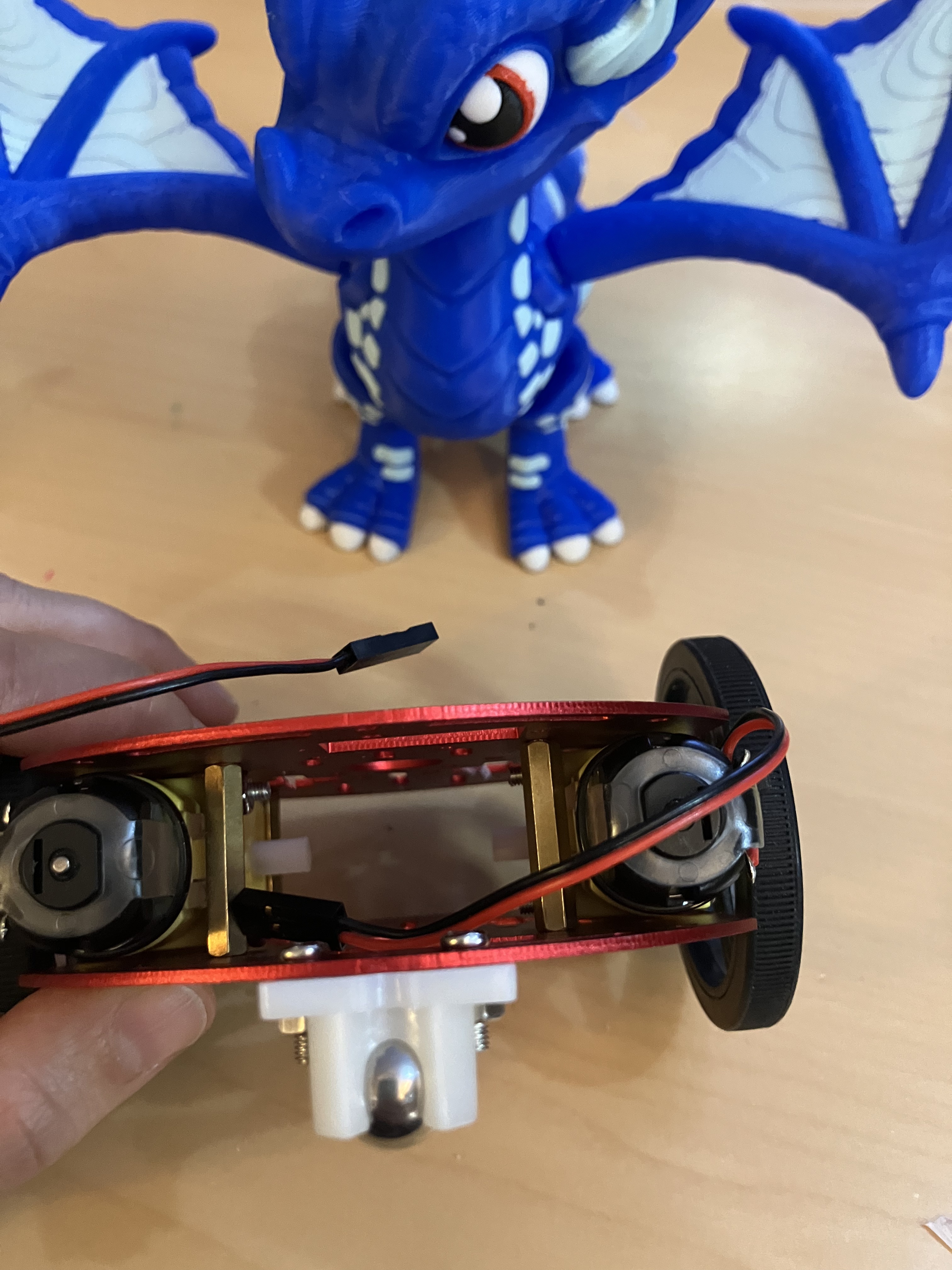
Also take a moment to make sure that your spacer bolts are in these positions, this is going to matter later:

Once you’ve got that settled, we’ll begin by attaching the battery pack. Grab that and then go ahead and open up your little bag of bolts and check it’s got everything you need:

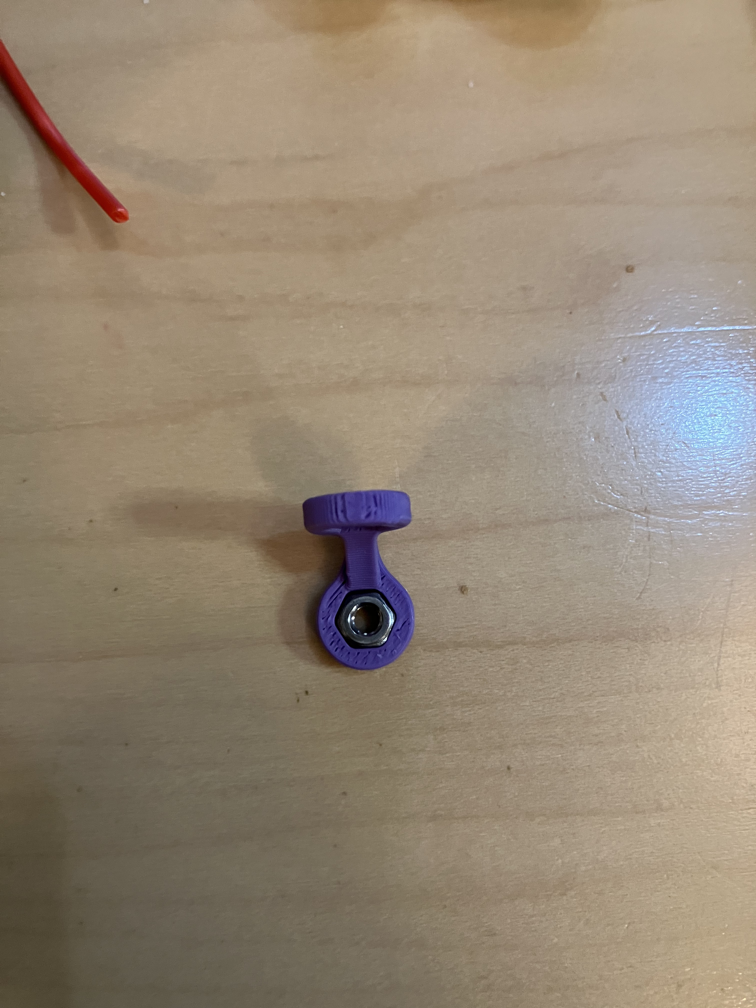
In addition to the bracket (which in this photo is purple, but yours is black), you should have two M3 nuts, a long bolt with a countersunk top and a smaller more standard looking bolt.
The bracket is designed to hold nuts in it to make your life easier, so you can start by fitting one into it:
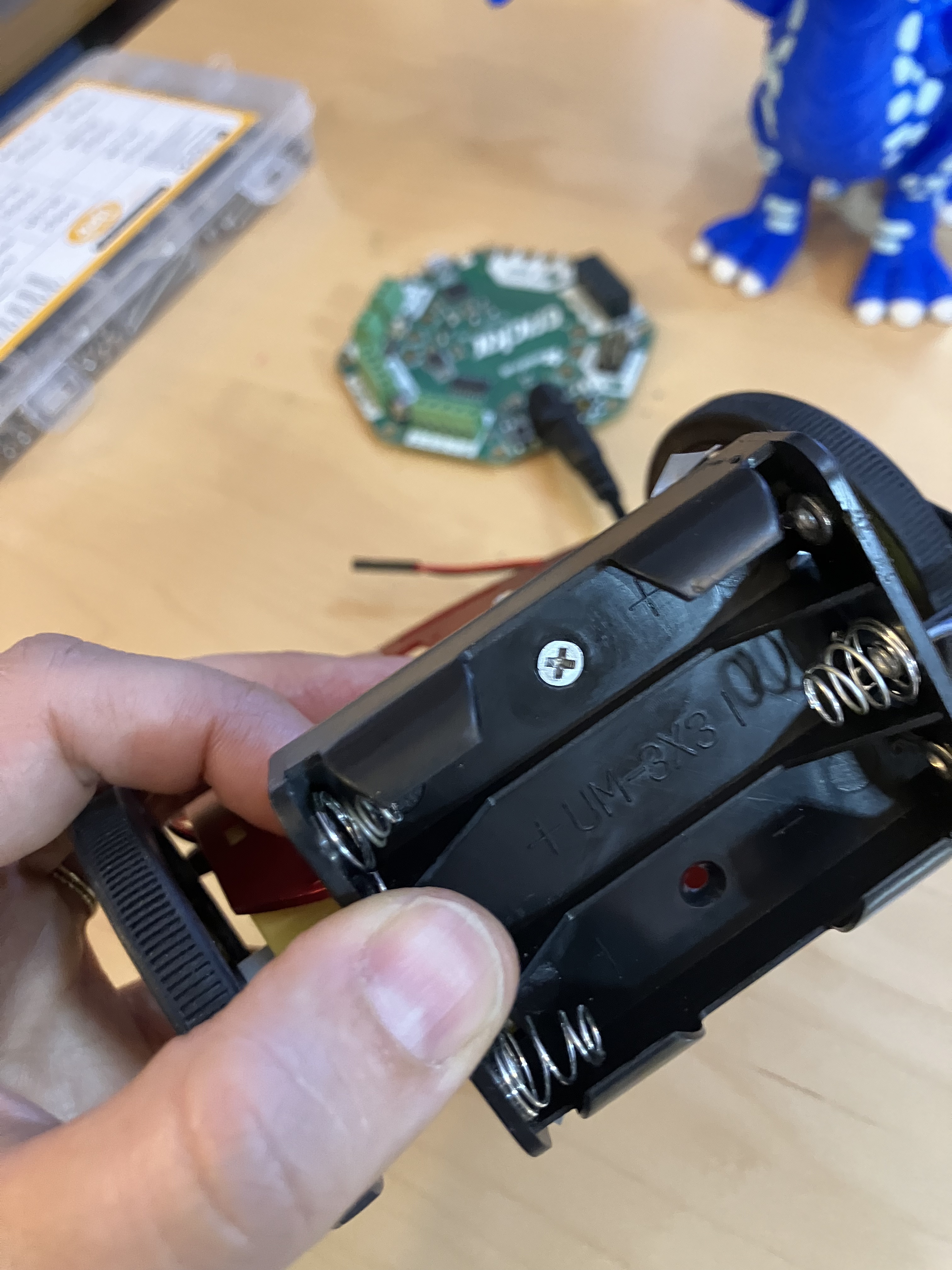
Then put the bracket on the back of your chassis, the opposite side from the ball bearing wheel, and attach it with the smaller, regular bolt. You want it to be in the hole on the very edge of the chassis:

Attach the battery pack to the bracket in a similar way, using the countersunk bolt. You want the bolt to lie flat inside the battery pack so that it’s not interfering with the batteries.


Next up is to assemble the CPX+ CRICKIT using the six brass stand-offs and the twelve screws that you can find inside the pink plastic CRICKIT package. Adafruit has a really excellent guide (with animation!) on this. The most important thing is to make sure that you attach the CPX the right way around. Start by attaching the stand-offs with six bolts:

Then place the CPX on top, making sure that the USB port on the CPX is facing the battery barrel on the CRICKIT, and use the remaining six bolts to attach it:
Double check you’ve got it on properly!
Now we’re going to use the 3M double sided foam circles to put it on top of the chassis. You’ll want to put the foam stickers in a stack like so (they don’t have to be neat, just somewhat near the center and one on top of the other):
Then place the CRICKIT/CPX system on top exactly like this, making sure to leave a little gap at the front (there’s a rectangular hole in the chassis, we’ll be using that to put in an ultrasonic sensor later).

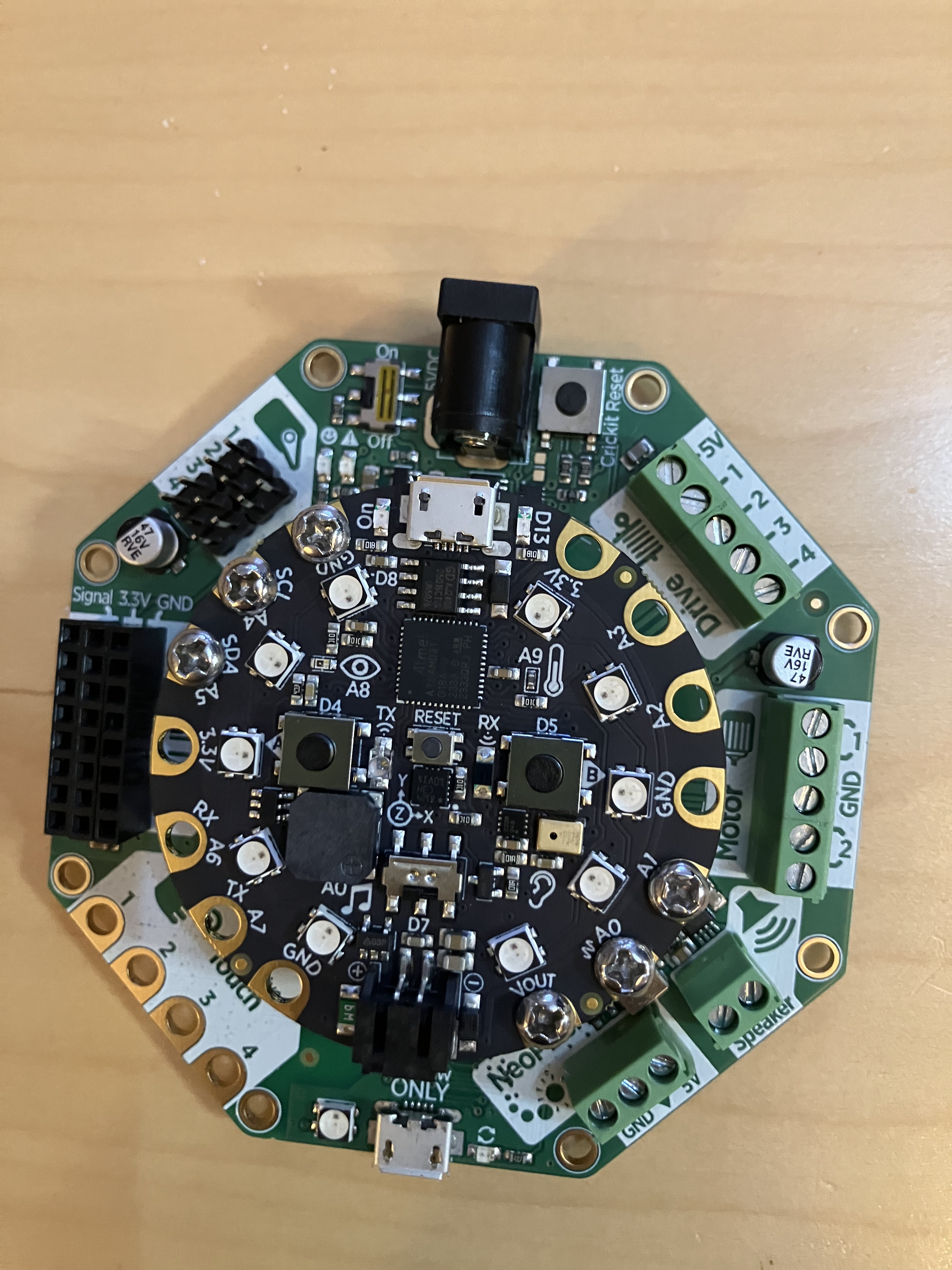
Now we wire it up (you can see in the photo above what it looks like when it is done). Take the four T-T jumper wires and use them to extend the motor wires, and then use your flat-head screwdriver to open up the screwblock terminal and insert each pair of wires. One set of wires should go to the left of the GND label, and the other to the right- it doesn’t matter which way you do it, as long as you keep the wires from one motor on one side and the wires from the other on the other side. You can also see the Adafruit wiring diagram:

Put the batteries in the battery pack, plug in the barrel jack, and you are good to go! The next part is to get your CPX running.
Before you go to the next round, verify that the on/off switch on the CRICKIT is set to OFF.
One final note: the CRICKIT has its own USB port, but we only use this to update the SeeSaw firmware (the special code on it that it uses to communicate with the CPX). The CRICKIT never gets its own code, so in general, do not use this port!
Software
Your CPX is going to need a CircuitPython upgrade in order to use all these nifty new ports. Adafruit has a special build just for the CPX+CRICKIT combo. Go to Circuitpython.org and search for the CRICKIT+CPX to grab it, or just follow that link. Updating is the same as usual- plug in your CPX (make sure you use the right USB port!!), put the CPX in bootloader mode and drag the new .uf2 file into it. Once you’ve reloaded the CIRCUITPY drive, go ahead and open up the Mu editor. We’re going to start by calibrating our motors. This code should make the two DC motors run forward at the same rate (ie, should make your bot go forward in a straight line):
import time
from adafruit_crickit import crickit

motor_1 = crickit.dc_motor_1
motor_2 = crickit.dc_motor_2

while True:
    motor_1.throttle = 1
    motor_2.throttle = 1
By now, you should recognize the sections of code here: we reference the crickit library, set up two objects named motor_1 and motor_2, and then loop an instruction for those motors, in this case, full speed ahead. Plug in and save your code, but- maybe nothing happens (nothing should happen). You get the blinky red lights, and if you check the serial, you’ll get an error message that says:
RuntimeError: No pull up found on SDA or SCL; check your wiringThe new CRICKIT library needs to communicate with the CRICKIT board, and it uses two dedicated ports to do so- the SDA and SCL ports (these stand for Serial Data and Serial Clock, and they are very important in general to the I2C protocol, you can read more about them if you like!) These are also known as ports A5 and A4, respectively, and can be used for other analog devices when they are not being for I2C communications. If you look at your CPX, you’ll see that these two ports are connected to the CRICKIT via bolts and standoffs.
But wait, if they are connected, why the error saying to check the wiring?
This is because the CPX code is telling it to expect a device on the other end that has POWER, and as you recall, we turned the CRICKIT off!
This error is the most common error I see students run into while using these robots. You want your CRICKIT to be off while you are updating code, but it’s easy to forget that the code won’t run correctly when the CRICKIT is off!
Unplug the CPX from your computer (yes), then turn on the CRICKIT, and your robot should move- but chances are, it won’t move forward in a straight line. This is the calibration part. For the rest of class, your goal is to get the robot to go in a straight line, and here is useful information about the code you are running.
DC motors are pretty straightforward little devices- they spin at a rate determined by the amount of power you give them, and in a direction determined by the direction of power.
This direction is set by two things: the wires themselves and the code. So if you want to change the direction a wheel is going, you can either swap the wires in the motor block that correspond to that wheel (I would recommend changing them at the T-T jumper intersect) OR you can change the code from 1 to -1.
Now for speed: the throttle function (so, motor_1.throttle for motor_1) is a percentage, so the value 1 = 100% (or full speed), 0.5 = 50% (or half speed) and so on. The two motors are not identical, so will likely need to adjust these two numbers to get them to even out.
More hints if you need them:
- If your bot is spinning around in a circle, that means one motor is going backwards and the other is going forwards. Try swapping wires on one motor, or change your code on one of the motors from postive to negative.
- If your bot is going backwards, that means both motors are wired backwards. Try swapping both wires, or change your code for both motors from negative to positive (or vice versa)
- If your bot is going forward but curving to the right or left, that’s because the motors run at slightly different rates (this is normal). Try changing the speed of one motor at a time until they even out.
Finally, you can look at the full Adafruit guide for DC motors to see all the things you can do.
