Lab 1a: Teacher Demo
Today’s lab is an introduction to basic electronic circuits and LEDs (light emitting diodes). We’ll start with a breadboard, then move to alligator clips, and then finally a sewn circuit.
First and foremost: for power and information, you’re going to use a tiny microcontroller called a GEMMA. It actually holds a whole powerhouse of computer code, but don’t worry, we aren’t getting into that yet. Today, we’re just going to get used to seeing it as the center of our circuit. Take out the bigger circuit board thing- this is the the GEMMA- as well as the battery pack and batteries, and set it up like so- plugging the JST (this is a brand name actually) cord into the large, off-white receiver:

Note that the battery pack AND the GEMMA have on/off switches on them. Turn them both ON to make sure you’ve got it going right (the GEMMA should blink a little) and then turn at least one of them OFF for now.
Next, go ahead and open your bag of materials for day 1, and pull out these items:

You have:
- six jumper wires – four that are transmitter/transmitter (T/T), and two that are alligator clip/transmitter (A/T)
- three single color LEDs – blue, white and green
- one RGB LED – frosted white
- three resistors
- a breadboard (not pictured above but you can’t miss it)
We’re going to start with a very basic circuit. Take a look at your GEMMA, and see that to the right and left of the JST power plug, it has a bunch of circles cut out around the edge, each with a gold area around them, and labelled with things like A0 or GND.
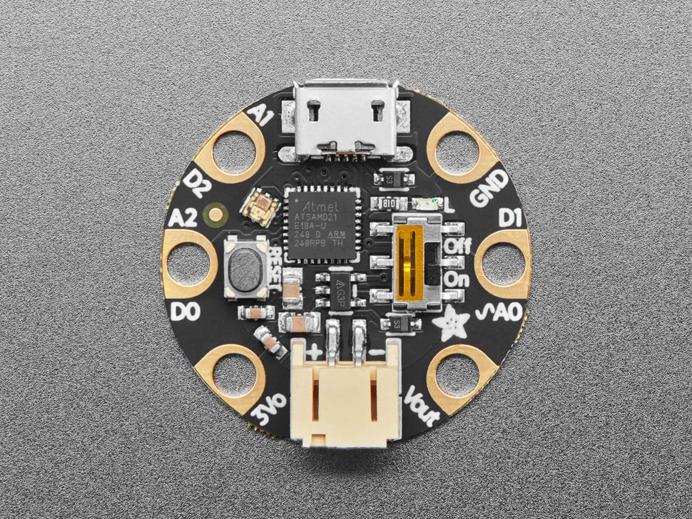
These are called a lot of things but most commonly I/O pins, ports, or pads. The GEMMA gets power from the battery pack and sends it back out as a regulated 3.3v current, so we’re going to use that current to power the LEDs by running wire from the power pad (labelled 3Vo) through the LED and then back to the ground pad (labelled GND).
Now, let’s look at your lights. These are Light-Emitting-Diodes, which means they only receive power one way. Pick the blue one up and look at it and you’ll see it has a long leg and a short leg. The long leg is the positive leg or anode, the short one, the negative one or cathode. It’s also got a bunch of other stuff inside that make it work.
You’re going to go ahead and plug the LED into the power rail on the side of your breadboard, with the long leg in the positive side (next to the red line) and the short leg in the negative side (next to the blue line.) Then take your two alligator/transmitter wires. Clip the red one onto the 3vo pad and plug its other end into the red rail (anywhere works! but I recommend the top for aesthetic purposes), and then clip the black one onto the GND pad and plug it into the blue rail. You should have this (note that in this photo I do not have the power plugged in, you can leave yours plugged in as long as it is off!):
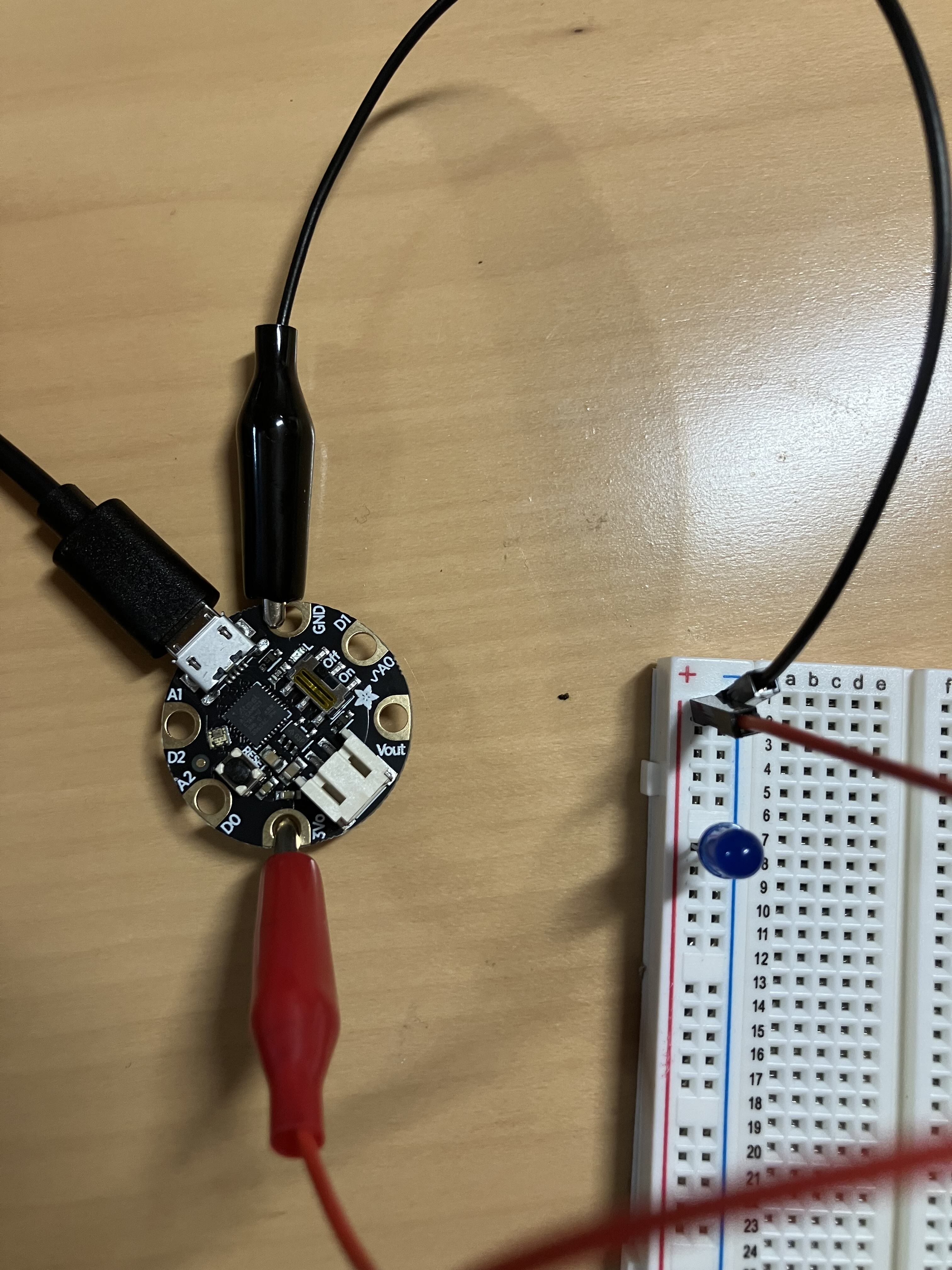
Double check your circuit looks like the above, and then turn on the GEMMA and battery pack. The light comes on!
The GEMMA is putting out enough power for a few lights, so go ahead and put the other two lights onto the breadboard. Remember the anode leg goes in the positive column and the cathode leg goes in the negative column.

So many lights! And these are in parallel, meaning it doesn’t matter if any of them burn out or if you remove them, the others still work. Move them around and see.
Alright, single lights are all well and good, but most LEDs we’re going to work with are what are called RGB LEDs- these are lights that have three smaller lights in them (Red, Green, and Blue) that you can light up at different levels in order to display thousands of colors. This type of LED combine some of the legs so that instead of six legs (one anode and cathode for each) you only have four legs, and all three lights share either their positive or negative leg. These are called common anode and common cathode RBG LEDS, respectively, and the two types are wired a bit differently. We’re working with a common anode, so we’re going to do what you see on the left here – including using some new components- resistors! Yours are light blue instead of cream colored, and they are a different value with different colored stripes, but the shape is the same.
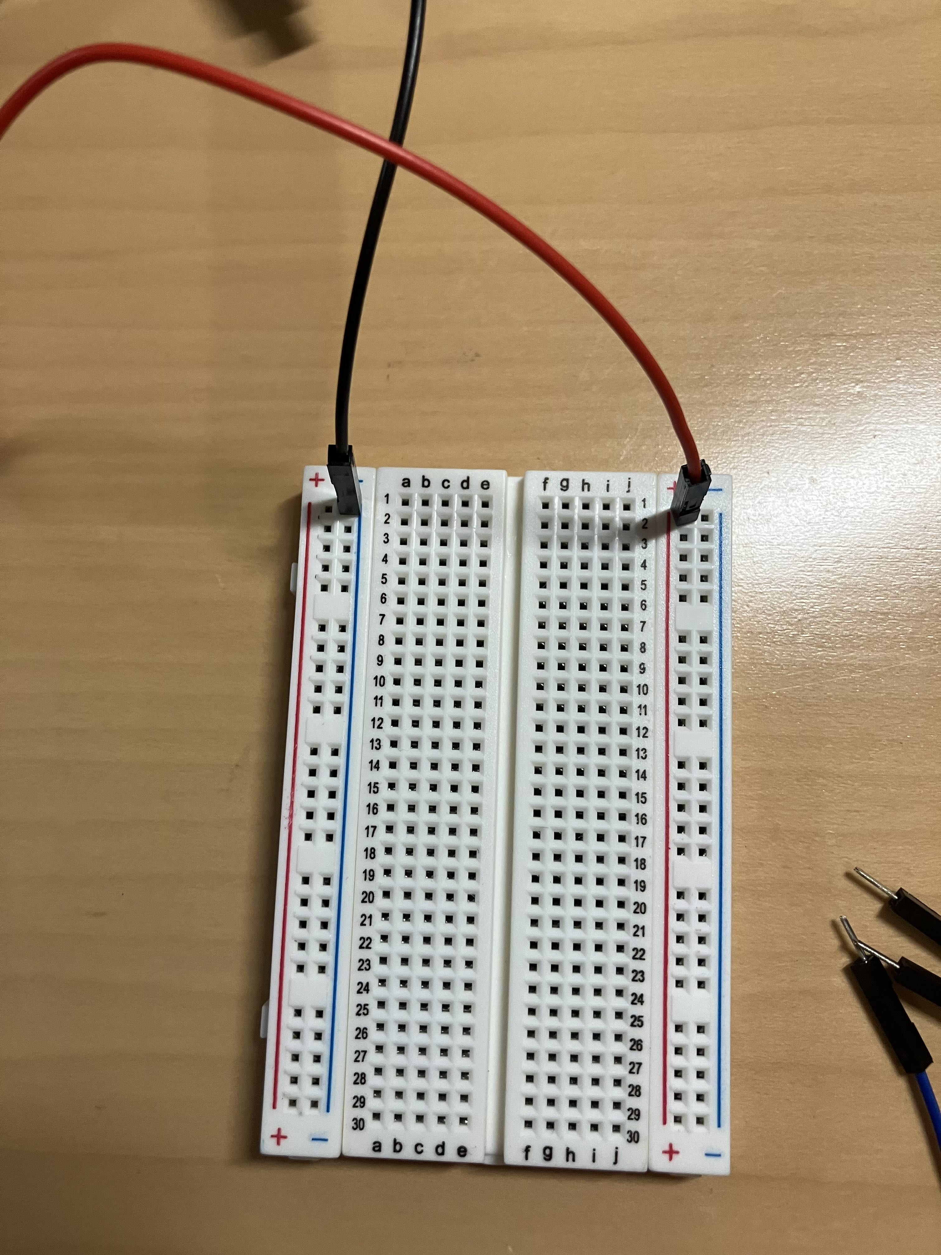
Turn off the GEMMA, clear your breadboard of your old components, and put the blue, white, and green LEDs aside. Grab your four remaining jumper cables (purple, green, blue, and black), your resistors, and your RGB LED, and lets get wiring. First, move the power cables (the black and red jumper wires that are going to the GEMMA) so they span the whole board, as so. You’re powering up the positive (red) rail on one side and the negative (blue) on the other. The picture only shows the breadboard side, so remember that these two cables are still clipped to the GEMMA (red to 3Vo, black to GND):
Next, you’re going to send some power across the board. While the left and right of the breadboard are wired as columns (I also refer to them as rails), the center is wired in rows, and these are labelled 1-30. (The columns a-j are labelled as well, but this is just so you can find an individual square – the connections never flow in these columns). Place your jumper wires like so, starting with the purple at the top, then green, then blue. I put the purple one in row 10, the green in row 15, and the blue in row 22 – it doesn’t matter if you do these exact rows, but they should be spaced about this far apart.
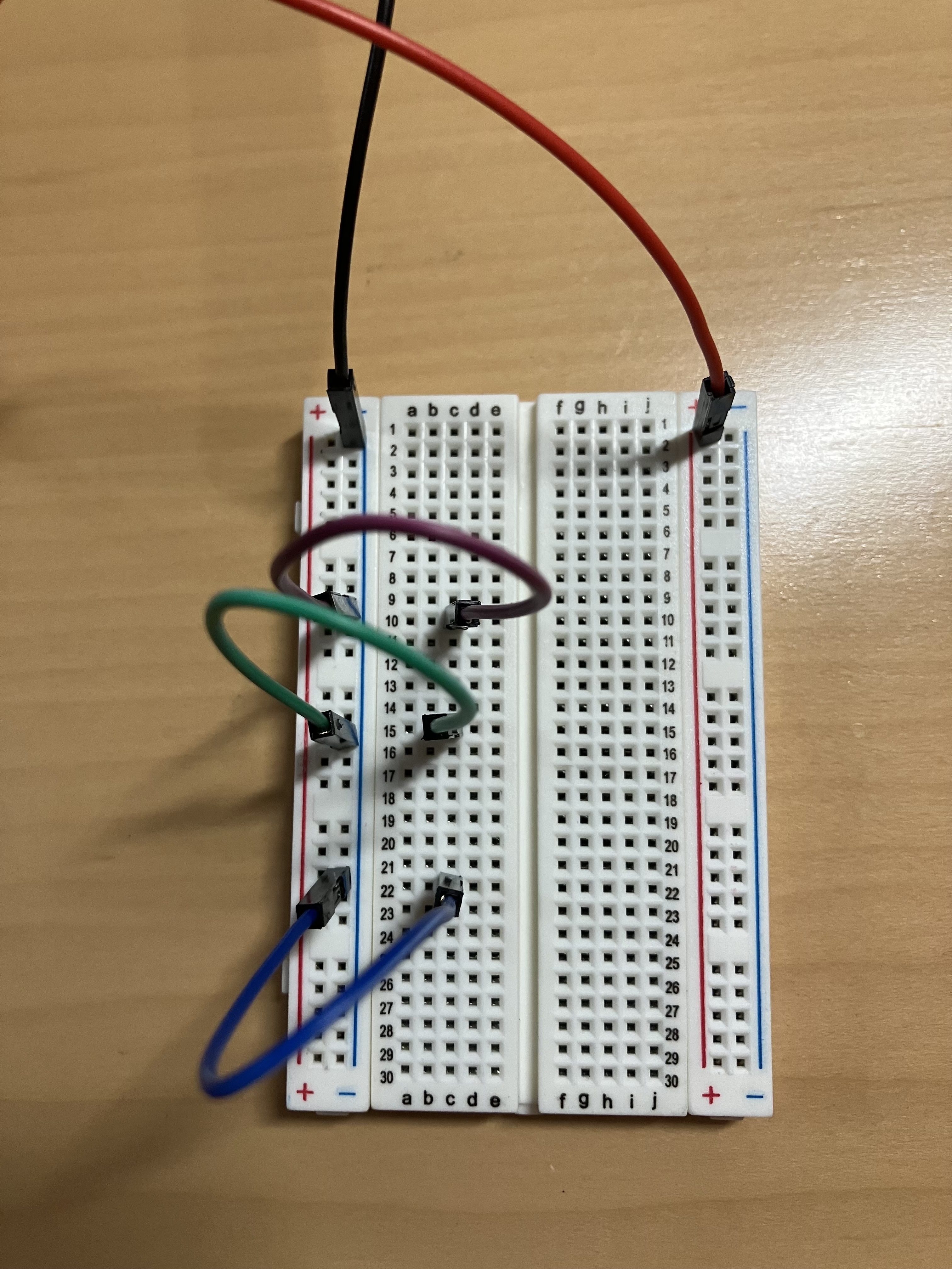
Look again at your breadboard for a moment, and note that the center has a break- the connection doesn’t actually go all the way across. We are going to use a resistor to jump that break. Your three light blue resistors are all the same value, and these, unlike LEDs, can be plugged in either direction. I find it easiest to start by bending the resistors into little U shapes (like this |_|) first. Then, take one, and plug one side into the same row on the same side as your purple wire, so for me, that was row 10, and then go over the break, and put the other into row 14. The next resistor connects your green wire (for me, 15) across to row 15 on the other side (in the same column as the first resistor, so for me, that’s column h), and the final one connects blue (for me, 22) to row 17, column h. Yes, that’s right, 17- you want to skip a row! 16h should be empty:

Why the empty row? Well, remember our LED has four legs, and one of them is common anode leg, the shared positive or power leg. Note that what we have done here is make three connections from the negative (ground) on the GEMMA – these correspond to the Red, Blue, and Green negative legs of your LED. The empty slot, corresponding to row 16, will be for power from the positive leg. You can put the RGB down next to the breadboard to see what I mean. Note that the longest leg is your anode, and that will go in row 16:

Plug the RGB in to column i, putting the top (shortest) leg into row 14, then the next into row 15, the longest into 16, and the last into 17. It may be fiddly, but once you get it in push it in firmly. The final step is to connect your power cord – take that final jumper wire, and plug it into row 16, column j – on the other side of the LED! – and then into the red rail. The two are close together so it’s hard to see in the photo:
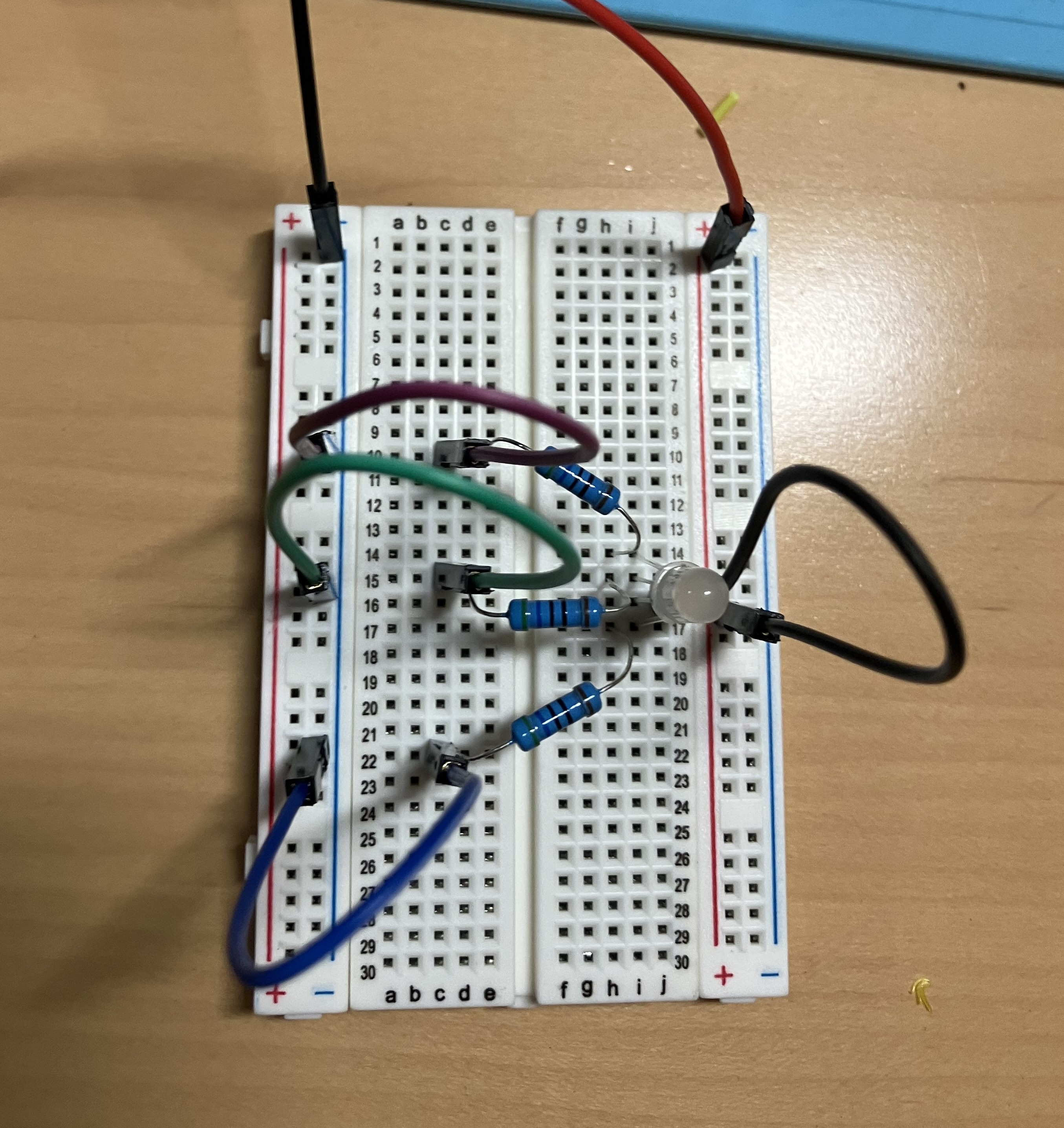
Now go ahead and turn on the GEMMA, and you will get- a white light! But why? Well, because R+B+G=full spectrum! You need to subtract the lights in order to get different colors. To do that, you can just plug and unplug the purple, green, and blue wires from the negative (blue) rail on the left side. Try different combos to see what colors you can make. Hint: there are six base colors for RBG light, three primary and three secondary (just like the red/yellow/blue and green/orange/purple you learned about when you learned about pigment colors).
Lab 1B: The neopixel
Having all of those wires is kind of annoying, though, especially if you are also trying to power hundreds of RGB LEDs to make fancy patterns. Enter the addressable RGB LED, also called a NeoPixel. Go back to your bag of supplies and pull out the other tiny chip looking thing. It’s sort of like the GEMMA because it’s a circuit board, but it’s much smaller and has no plug ports in it. Grab the alligator cables too: these have clips on both sides (A/A):

Unhook your GEMMA from the breadboard system (you won’t need this system, so you can do what you like with it for now.) We’re going to use a slightly different circuit this time. Before, we were using the 3.3volt power, but this time, we’re using the 5volt power. This is labelled Vout on the GEMMA. We’re also going to use one of the data pads – specifically A0. This pad is telling the NeoPixel how much power to give each of the colors (RGB). It’s already coded, we’re just plugging it in. Clip the red wire to Vout, the black to GND, and the white to A0:
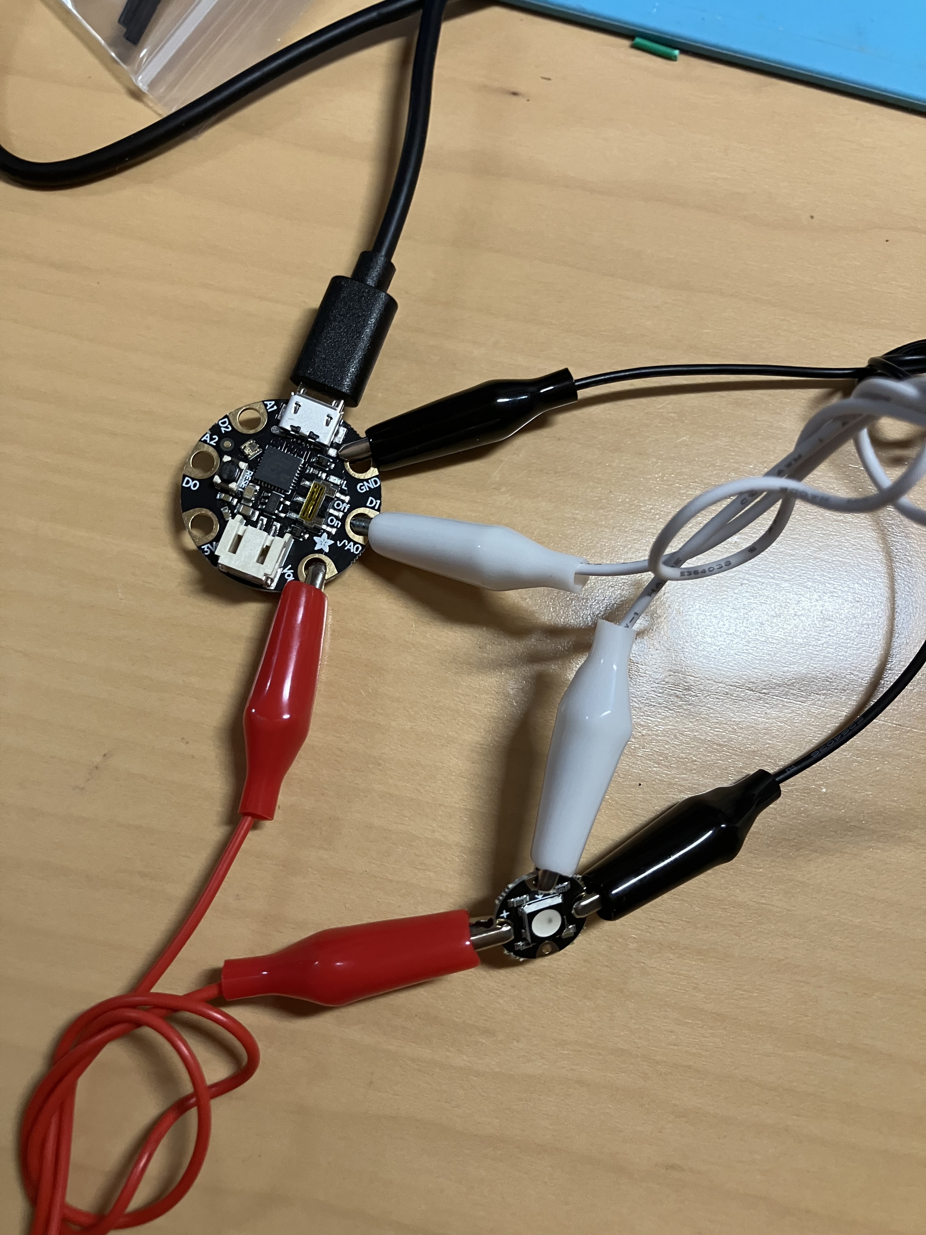
The other ends of the alligator clips will go on the teeny, tiny NeoPixel ports. They look like miniature versions of the ones on the GEMMA, and the labels are, correspondingly, tiny. The red wire goes onto + (connecting Vout to +), the black to – (connecting GND to -), and the white goes to the arrow that points INTO THE CENTER OF THE PIXEL:

Now, power up that GEMMA, and see the blinky blinky! Wow!
But this contraption is huge and… well, kind of annoying. Right? Here’s why: the secret I have kept from you is that these components are not designed to be used with wires- they are actually sewable components, used for wearables and soft circuits. So your final step is going to be to transfer this circuit to fabric. (Wow, Prof, is that why we’ve got this fabric in our kits? Why yes it is.)
Pull out your fabric, needle, and the length of thread. You should also have a set of snips so grab those too. This is a special conductive thread, made of stainless steel – it’s midway between a wire and fabric thread. If you are used to hand sewing you will find it is a little stiffer than cotton or polyester, more like a thick nylon thread. You are going to use a single length- don’t double up the thread.
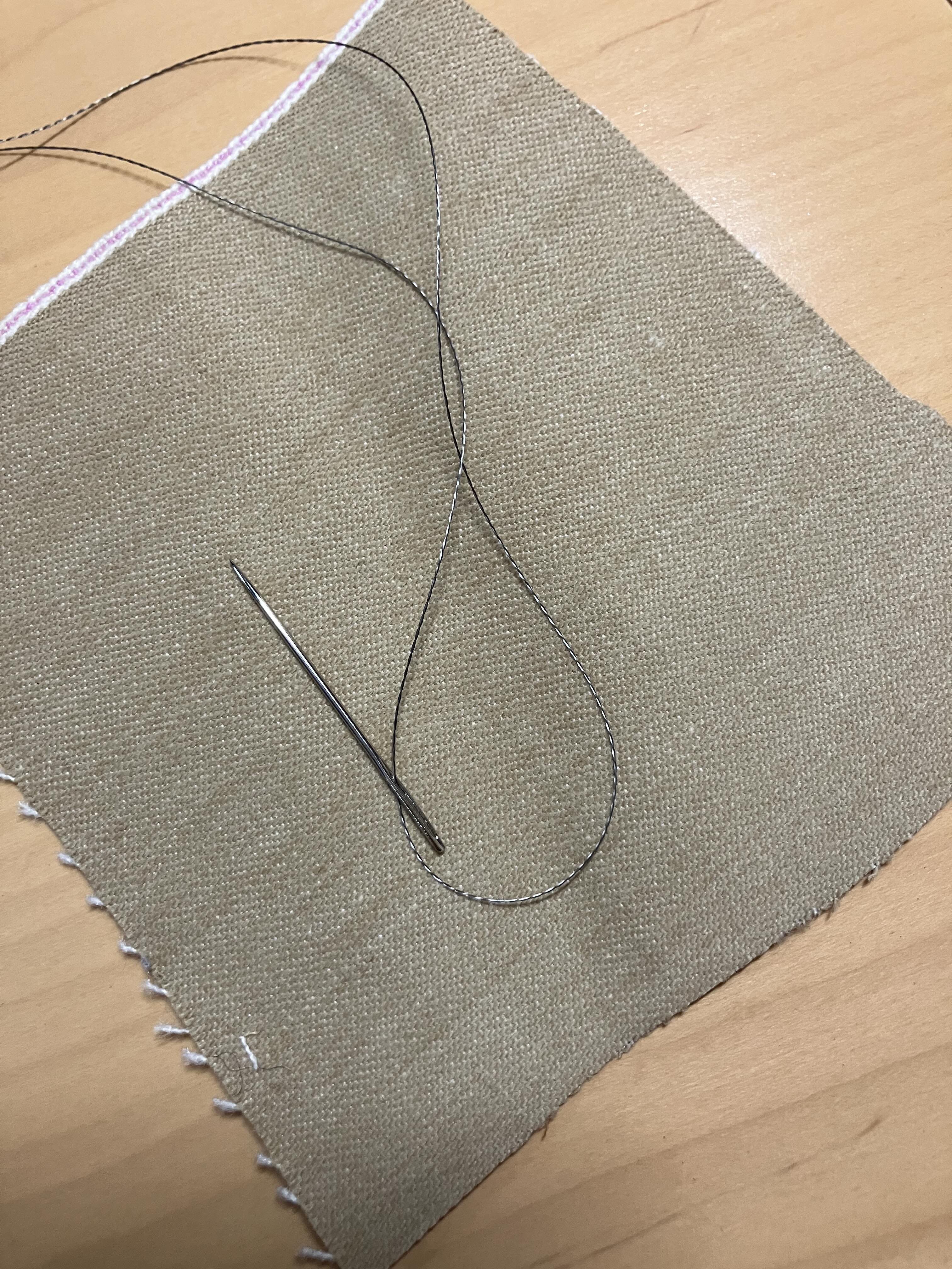
Sewing conductive circuits is like embroidery in many ways, but has some important differences. The biggest one is that you want to make absolutely sure that you do not cross the threads. Each of these jumper cables is going to be replaced by a length of thread. The thread cannot be connected together at all! So don’t jump ahead, please look at the photos. You’ll be sewing the GEMMA and NeoPixel a little bit apart- I put the GEMMA in the upper left corner and the NeoPixel to the right and below it. Here is the end result, for reference:
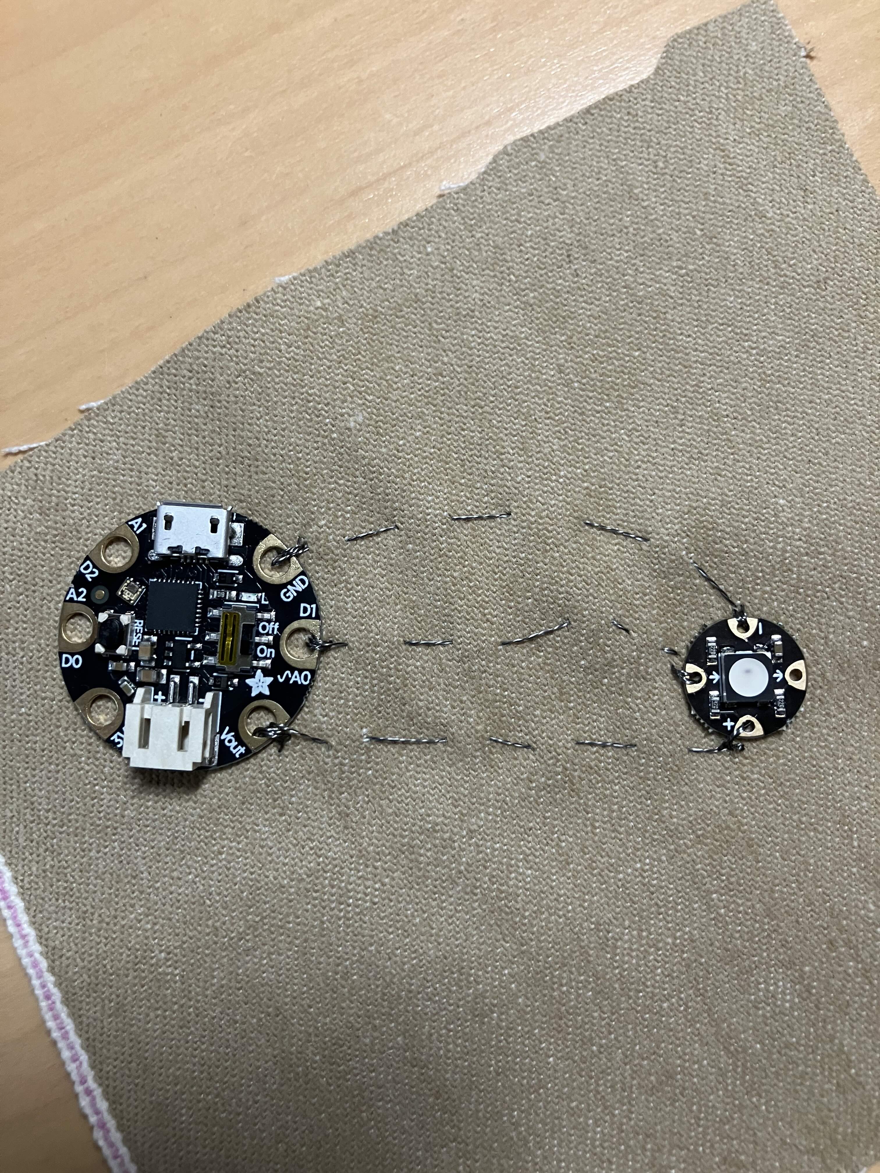
Start by sewing the GEMMA in place through the Vout pad, like so. You want to loop through the GEMMA three times. You don’t need to knot the thread to start but you can if you find it hard to hold in place. The first photo shows the loop, the second is after I pulled it tight.
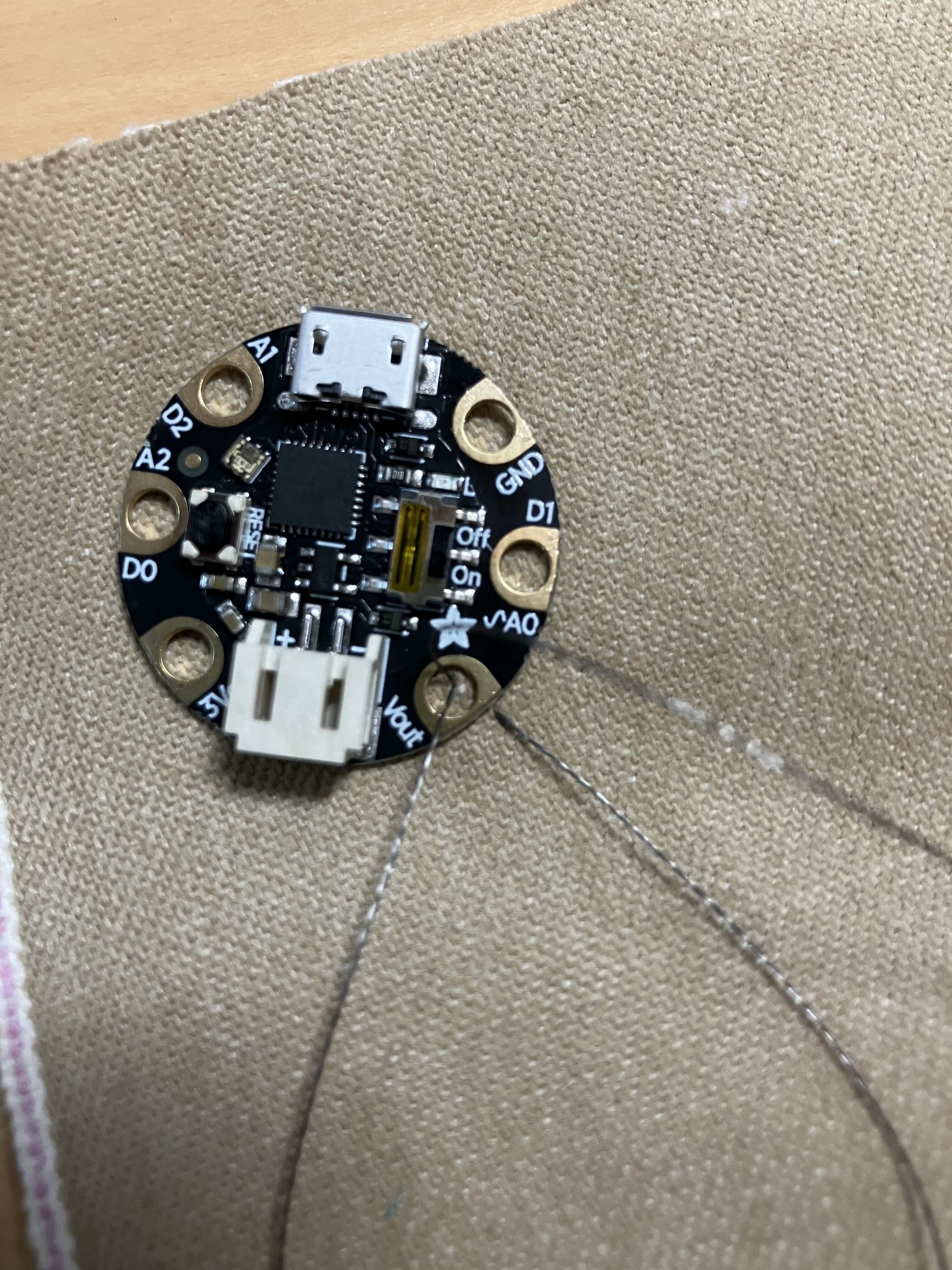

Do three of those, so you’ve got a nice little knot going:
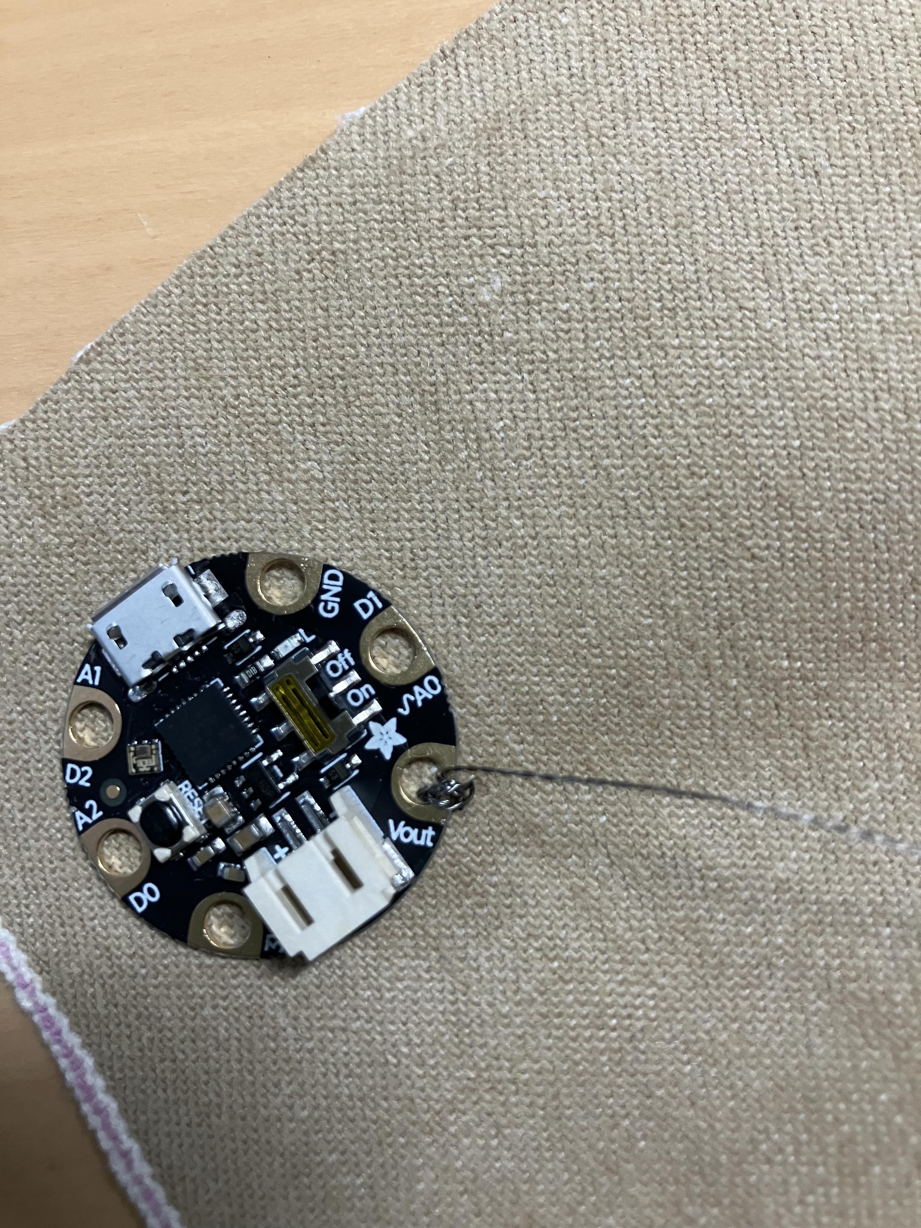
Now you do a running stitch (a simple up and down) through to where you want the NeoPixel to be. Remember, this thread is replacing the red alligator jumper cable – so it’s going from Vout to the + sign on the NeoPixel:

Then go ahead and sew through the + pad the same way you did with the Vout pad. Make about three loops. To tie off, you want to loop through the back side – that is, flip the fabric over so the GEMMA and NeoPixel are down- and make a simple knot, like so: (Photo is of the back side of the fabric!)

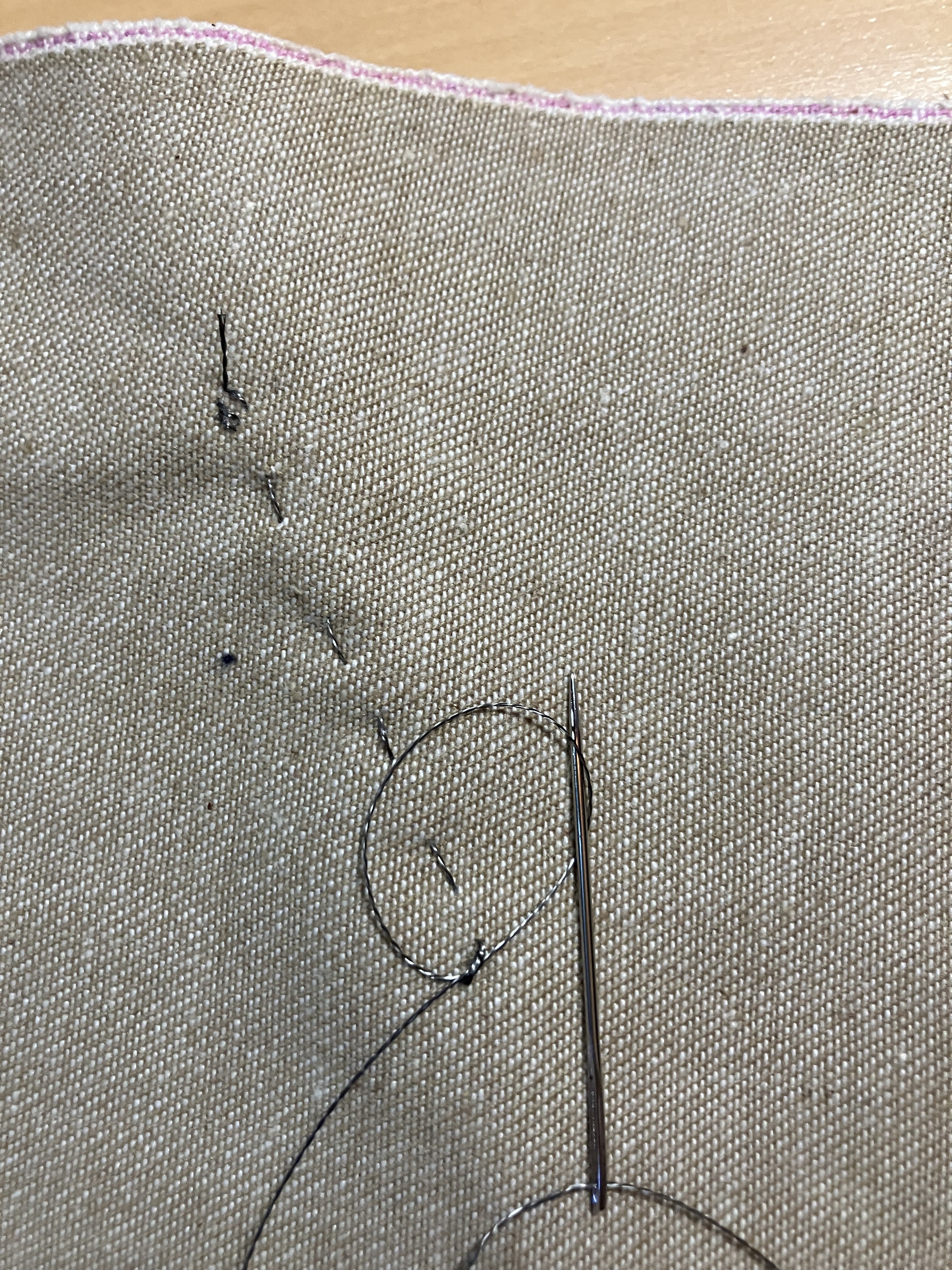
Once you have tied the thread securely, snip it off. The wires must be discreet wires. A continuous wire is a continuous connection!
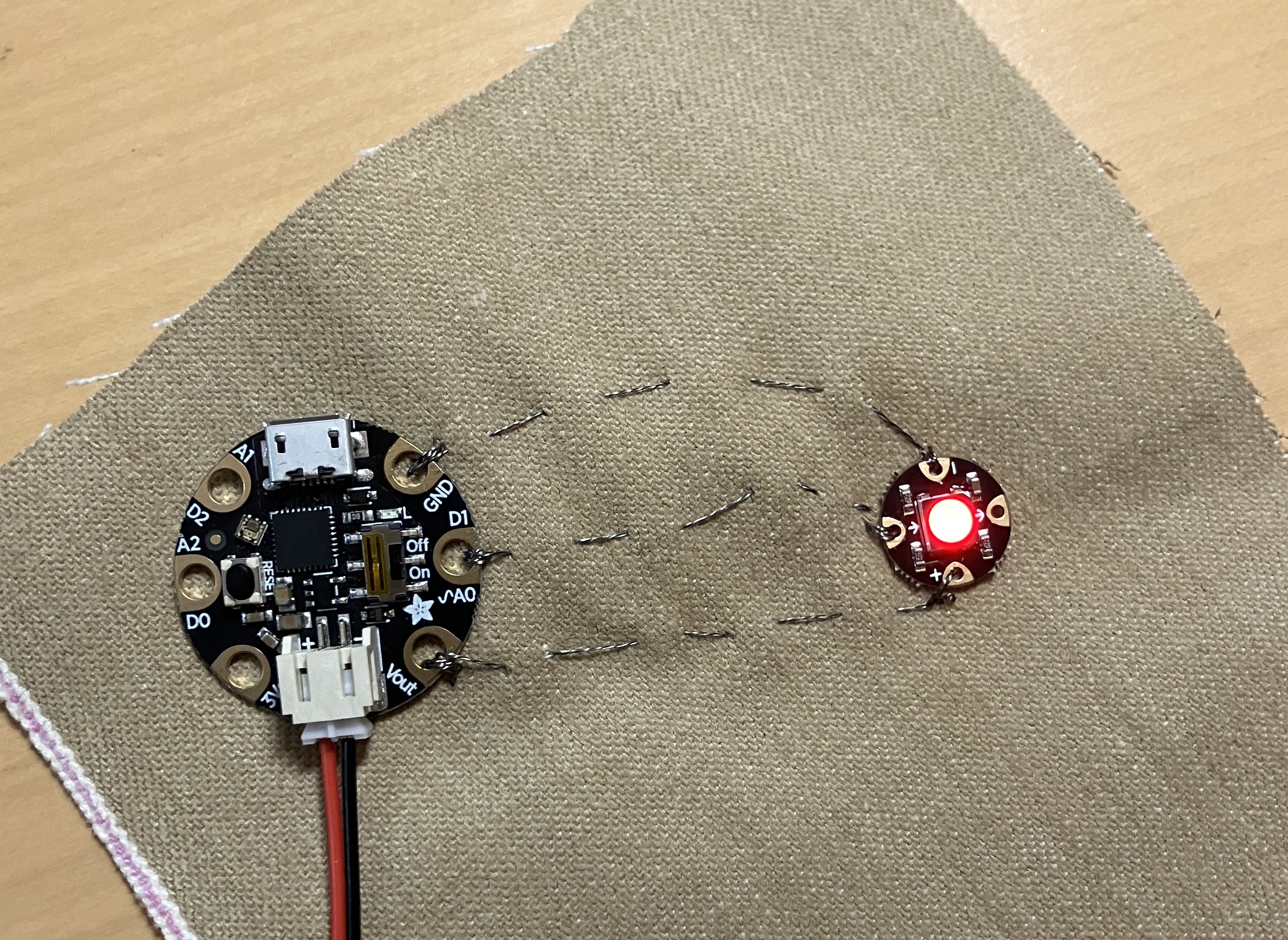
Starting at the beginning again, make two more sewed lines the same way, connecting A0 to the arrow pointing in and GND to -. Final result looks like this:
Note how all of the threads are separated! This is the back side:

Trim off any trailing ends, because crossed wires will cause a short circuit.
Once it’s clean, go ahead and plug it in and light it up!
Congratulations, you’ve made your first wearable electronic. Now, if you want an extra challenge – there is a second NeoPixel in your kit. You can sew it in series after the first one. Sew from the + on the first NeoPixel to the + on the second, from the – on the first to the – on the second, and from the OUT arrow (the one that is not used yet!) to the IN arrow. Yes, the second NeoPixel will be attached to the first, not to the GEMMA itself! The issue is, of course, that the light will not go on, and that is because the GEMMA isn’t sending code for two pixels, just for one. But you’ll fix that in the next lesson…
Next up, learning CircuitPython!
